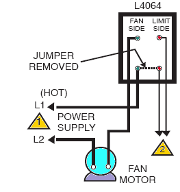
Replace sealing compound after routing wires through the bushing. Furnace fan limit switch control.
The source is at the ceiling outlet box and 3 wire cable runs from there to the switch box.
You can find out more Diagram below
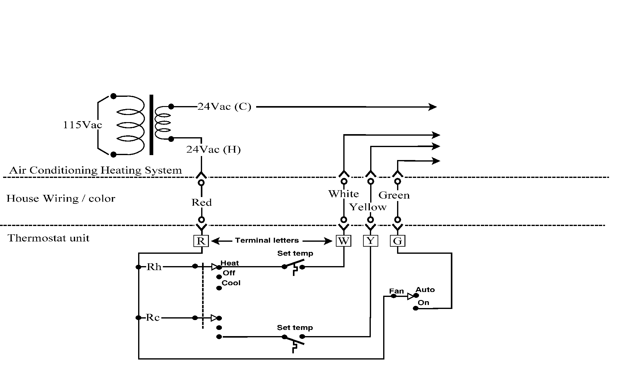
Fan cycle switch wiring diagram. Bryan ohio 43506 step 3. 7960 434d page 2 of 7 figure 1 wiring diagram step 12. Ceiling fan dimmer switch diagram.
Hunter 3 speed fan switch wiring diagram collections of wiring diagram for ceiling fan speed switch new wiring diagram for. In a typical installation the white neutral fan wire connects to the white neutral circuit wire and the black hot fan wire connects to the black hot circuit wire. Ground connection diagram is shown separately.
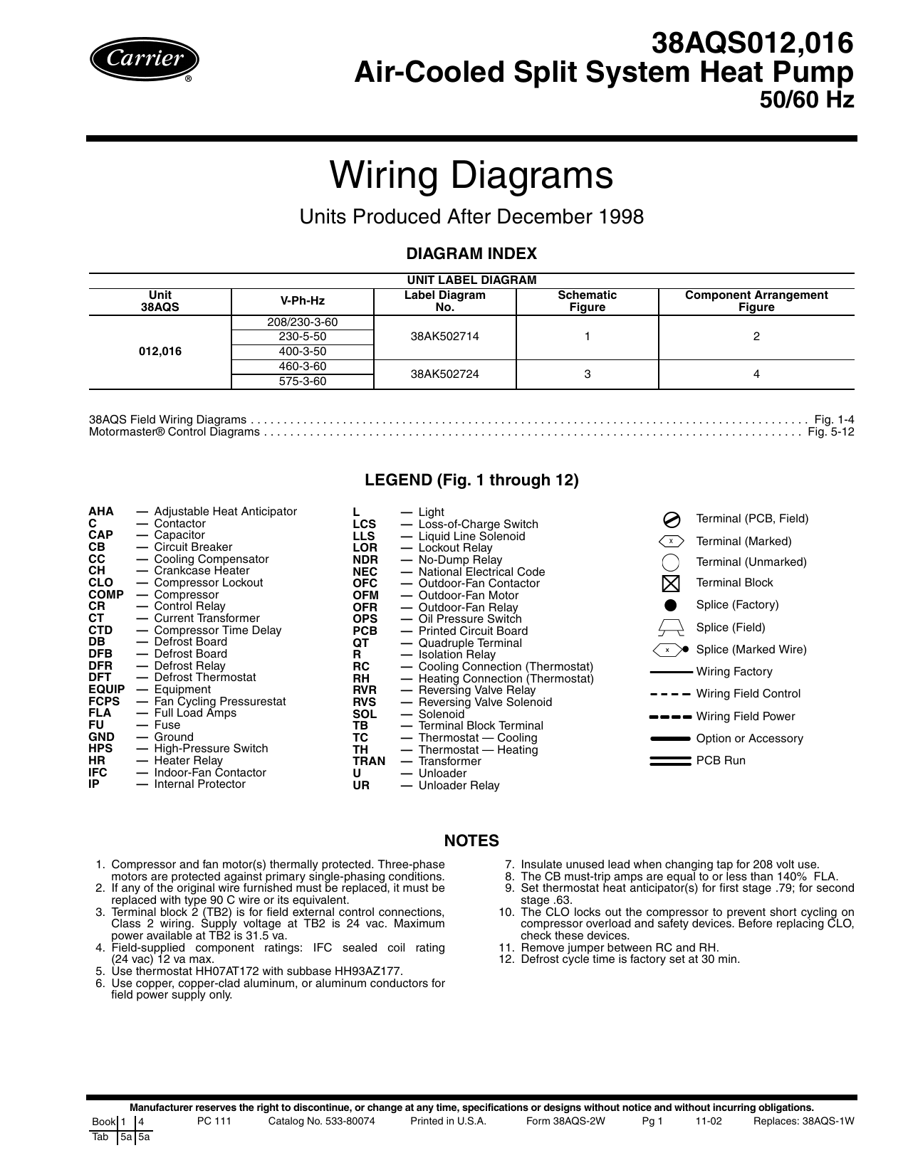
What ois a furnace limit switch. Installation instructions cma 13a low ambient fan cycling high and low pressure control and compressor control module with time delay bard manufacturing company inc. Fan wiring diagram best unique 3 speed ceiling switch hunter.
Through wire holder as shown in figure 2 3 or 4 step 2. The neutral from the source is spliced directly to the white wire on the fan kit and the cable. This wiring arrangement allows for lowering the lights with a dimmer and controlling the fan with the built in pull chain.
The burner may on some systems cycle on and off periodically while the warm air blower continues to run. How to wire a single switch ceiling fan. The low pressure switch wire to terminals lpc of the compressor control module.
Connect the remaining ceiling fan wires to the circuit wires following the fan manufacturers wiring diagram. Route low ambient control wires up through the bushing in the bottom of the control panel. Wiring diagram for a 3 speed ceiling fan switch new hunter 3 speed.
3 speed fan switch diagram best 10 ceiling wiring free at typical. How to install adjust or repair the furnace fan control or furnace limit control. Installation instructions cma 6 low ambient fan cycling control bard manufacturing company inc.
The fan control switch usually connects to the black wire and the light kit switch to the red wire of the 3 way cable. In this diagram the black wire of the ceiling fan is for the fan and the blue wire is for the light kit. For the bc7070 shown above here is a wiring diagram and very brief manual.


0 comments:
Post a Comment